| Malibu Hydro...Our existing system | To index |

|
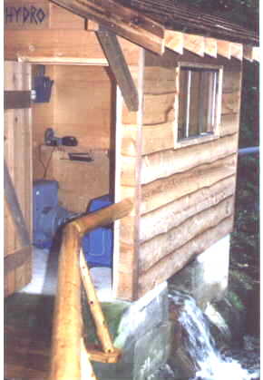
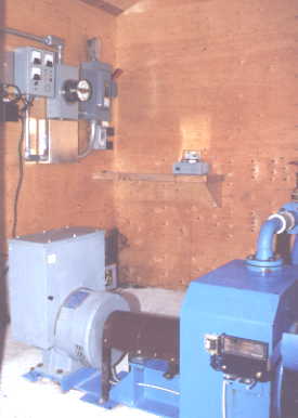
Malibu already has a functioning hydro electric plant! In 1994 when we got serious about pursuing our dream of energy independence, we built a small 12 kW system to supply the camps electrical needs during the winter months. This was done as much for its practical use as for a demonstration system so we could gain experience in the use and operation of a hydro plant. The system has been in operation for part of every winter, and has now generated the equivalent of $4,800.00 in diesel produced electricity. The story of our building this project has been published in the June 2000 issue of "Home Power Magazine", copyright by Peter Talbot. The unedited text is also presented here. See the section on Beyond Malibu, under 'other sites', for more on hydro in Princess Louisa Inlet, or visit www.microhydro.ca for information on other projects. Note, this equipment is still in operation at a slightly different site. See section # 9 entitled 'New life for an old friend" in the 'Other Hydros' section. From Water to Wire, Building A Micro Hydro System For 500 miles the remote and storm battered coast of British Columbia winds its way north in a torture of craggy cliffs and isolated fjords. Drenched by the wettest climate in North America, and situated at the foot of the ice covered Coast Mountain range, this wild isolation provides a perfect setting for tapping into the endless supply of free energy produced by falling water. Tucked among these mountainous wilds 100 miles north of Vancouver, lies the picturesque resort camp of Malibu Landing. Here, 45 years ago a wealthy entrepreneur built the Malibu Club as a private resort for the stars of the California film industry. Boasting all the modern conveniences of the time, and situated in a beautiful location, the resort operated for a few brief years before being abandoned due to unpredictable cool Canadian summers and fierce winter storms. Following the closure, the camp was converted into a summer resort for high school age young people and has functioned in that capacity for over forty years. Since its early beginnings, the isolated site has been subject to the relentless roar of diesel powered generators and high cost of barged in fuel. Surrounded by snow covered mountains up to 8500 feet high, and blessed with steep flowing creeks, the site was a natural for a micro hydro power plant, and yet after all these years one had never been developed. I had been visiting the area for a number of years and saw the potential for a development that could reduce their dependence on diesel fuel. For most of the winter a thin water fall cascades over cliffs 1000 feet above the camp. Though dry for most of the summer, this was of interest (to me) as a potential source of hydro power for the winter months. Since the camp is closed in the winter, the power requirement for the few year round residents is small, averaging under 10 kW, and might just be handled by a small hydro plant fed from this seasonal flow. A decision was made to conduct a rough survey of the terrain, and then collect stream flow data over the course of the following winter. If the flow proved to be sufficient we would begin construction the following summer. THE SURVEY: One of the first steps in the design of a hydro plant is to determine if there is sufficient flow available to make the project worthwhile. Fortunately, the wet winter season corresponded with the demand that would be placed on the system, and long term casual observations suggested that there would be adequate flow for most of the winter. The caretaker had been keeping an unofficial visual record for almost ten years and could compare the estimated flow on any given day with seasonal norms. This proved a great advantage when we installed an accurate measuring device at the falls, as we could then compare actual flows with past observations. HEAD MEASURED The second key ingredient to a successful hydro project is the total available change in elevation over which the water can develop pressure in the pipeline. We first measured this 'head', or elevation drop by means of a sensitive altimeter, and then by use of a hand held clinometer level and a 15 foot survey rod. The route the pipeline would take was more or less obvious, so we followed this as we carefully took each reading off the rod. As we leapfrogged up the hill the exact elevation was marked on prominent land marks as a permanent record. The use of the rod and level gave considerable accuracy over the distance, which traverses over some really rough terrain. Two elevation surveys were made to check for error and the results tied within a foot, close enough considering the method used. When all the surveyed elevation steps were added up the total to the base of the falls came to 639 feet above the proposed powerhouse floor. The altimeter reading agreed within 10 feet, and provided a good check against any gross errors. This elevation is on the high side for the typical micro hydro installation, but it would allow us some margin in where we could locate an open filter box and start the pressure penstock. Increasing height raises the operating pressure, and hence the power output. However, it also causes the turbine to spin faster, increasing with the square root of the height. There are implications imposed by this which effect the turbine diameter used, the desired output frequency, and the pressure rating of the piping. PIPE SIZED To measure the overall distance we used a 100 foot survey tape and again, marked the distance along the route. The total came to 2,200 feet, of which about 2,000 feet would form the pressure penstock. Determining the distance was much easier than measuring the exact head, but it too had to be done carefully as we planned to use pre-cut steel pipe lengths in the lower section. The majority of the pipeline was to be high density polyethylene pipe (HDPE). Since the static water pressure would be increasing as the pipe line descended the slope, we had to plan on where we would change to the next greater pressure rated pipe. We did this by dividing the slope into 6 pressure zones and selecting the appropriate pipe thickness for each zone. This PE pipe is extruded in various thickness. Often the pipe is rated by a series number, giving its safe sustained working pressure. Another system commonly used rates the pipe by its dimension ratio, which compares the pipes wall thickness to its diameter. We planned to use DR26 in the low pressure section, which is the same as series 60, all the way up to DR 9, which is equivalent to series 200. Beyond that, the wall thickness increased enough to significantly reduce the inside diameter. This would cause the water flow velocity to increase, resulting in greater friction and hence losses, so a strong, thin walled steel pipe became a better choice, and cost less. DETERMINING THE REQUIRED FLOW: Since the survey was done in summer when there was just a trickle of water flowing, we did not have the actual flow data to perform calculations to determine power output, efficiency and pay back time. However, having a fixed budget to work with and knowing the head, distance, penstock profile and power requirement, it was possible to design a system based on a minimum anticipated winter flow. Calculations showed that half a cubic foot per second, or about 225 US gallons per minute over a net head of 500 feet would produce an output of 12 kW and make the project well worthwhile. A simple formula to estimate electrical power produced from falling water in an AC producing hydro plant of this size is as follows: power in kW = (Q * H / 11.8) * N where Q is in cubic feet per second, H is head in feet, N = overall efficiency, typically 60 % in a small , well designed system. Another version of the power output formula gives ... power in watts = (net head in feet * flow in usgpm) / 9 < this formula already takes the efficiency into consideration.> For this site, the result is : ( 500 feet * 225 usgpm) / 9 = 12,500 watts (or 12.5 kW ) MEASURING THE ACTUAL FLOW. In order to get an accurate record of the flow profile over the winter, we constructed a wooden tank equipped with a "V" notch weir and placed it below and to the side of the falls. A length of 6 inch diameter plastic pipe was secured in the channel to catch the majority of the runoff and direct it into the box. The depth of the water flowing through the calibrated "V" notch weir gave an accurate measure of the flow available. Details on building various weirs are available in many of the hydro power texts. We used a 90 degree 'V' notch weir cut out of a piece of sheet metal. Table # 1 shows the flow in gallons per second per inch of depth through a small V notch weir . inch 1.0 1.5 2.0 2.5 3.0 3.5 4.0 4.5 5.0 5.5 6.0 6.5 7.0 7.5 us/gallons .04 .10 .21 .36 .57 .86 1.2 1.6 2.1 2.7 3.3 4.0 4.8 5.7 Table 1 A sensitive water level monitor was installed in the box and this was coupled to a radio transmitter which would relay the flow conditions down to the camp every few hours. A modified receiver and some additional electronics output the level to a numeric display, and this could be read off and recorded by the caretaker. He would then compare this accurate flow reading to what he observed flowing over the falls, and relate this to his ten years of casual observations. As the long wet winter set in, it soon became clear that there would be more than enough flow to make the project viable, so we began to design the system. EQUIPMENT, OUR SHOPPING LIST: Once we had the approvals to build the project and had established a preliminary budget of $15,000, the next phase was to order the necessary hardware. We were fortunate in that most of the suppliers were willing to give us jobber prices, since Malibu operates as a non profit organization. Since we had done an accurate survey we could order the pipe to the exact length and pressure rating that we required. We went to the suppliers before ordering the materials to check out the quality of the steel pipe and to be sure we would be able to handle the weight during construction. Pipe lengths of 20 feet weighed 180 pounds and would have to be carried by hand over very rough terrain. The four inch diameter polyethylene plastic pipe was ordered in 40 foot lengths. The pressure ratings varied from 60 pounds up to 200 pounds with a safety margin of 25%. Transporting the pipe was expensive as it required a 40 foot truck to get it to a suitable waterfront dock where a landing barge could be loaded. The long lengths did, however, cut down on the number of joins we had to make. One of the advantages of using Polyethylene pipe over PVC is that the working pressure can be close to the pressure rating of the pipe itself. This is due in part to the elasticity of the plastic used, which will absorb the shock wave, or water hammer, generated if the water flow is forced to change velocity abruptly. This effect causes a momentary pressure rise which travels up the pipe, and has the potential to do permanent damage, even bursting a more rigid pipe. To further reduce possible damage to the pipe when shutting off the flow we obtained a slow acting 4 inch gate valve. This was picked up at a scrap yard for 50 dollars! With a pressure rating of 500 pounds, this valve would have cost many times that if purchased new. PELTON WHEEL: The high head and relatively low flow rate of our site would be best handled by a pelton type of turbine. Since our operating head was to be between 500 and 550 feet, and we wanted the rotational speed to be 1800 rpm suitable for direct coupling to a generator, the turbine should have a diameter of approximately 10 inches. When under load, this diameter wheel would rotate at the correct speed, and the direct coupling would afford the maximum efficiency. We looked at three manufactures of turbines and got firm quotes. Each machine had its own merits, and costs were roughly equal. We settled on a local manufacturer, the chief reason being their proximity to, and familiarity with our site. They also had a turbine runner with the correct pitch diameter and bucket size to exactly match our site characteristics. The turbine was ordered as a package together with a 14 kW, three phase Lima brand generator. CONSTRUCTION: INTAKE WORKS: Intakes are usually the most difficult aspect to design on a micro hydro project. Seasonal variations in flow can range from a trickle in late summer to a raging torrent in winter, and on the steep mountainous terrain of the west coast, many a concrete intake structure has vanished following a heavy downpour. With this in mind we thought about ways we could minimize the construction required, and to work with the natural lay of the land as much as possible. It was obvious that ice and rock falling from the frozen lip of the falls high overhead would destroy any structure we built. What was needed was an intake that was formed as much as possible from the bedrock buried beneath the boulders and gravel below the falls. Following some excavation we were able to take advantage of the sloping granite bedrock down the hill from the base of the falls, and out of the direct line of fire from falling ice and rock. Here we built a low wall of reinforced concrete to divert the flow into a small pool enabling us to pick up even the smallest flows. The pool and wall was then back filled with large rocks. Falling rock and ice would then pass over the low wall leaving it undamaged. From the pool at the 600 foot elevation we ran 4 inch plastic pipe for 200 feet across and down to a level spot at the 550 foot elevation. Here we relocated the 5 foot long wooden box that was used to measure the flow. This was then equipped with three sizes of filter screens and a valve in the bottom to allow for the flushing of any sand and gravel. Excess water is passed through a narrow 1 inch slot cut into the top 12 inches of the tank which forms the overflow. This replaced the 'V' notch weir and gave better sensitivity for the level sensor. A pressure transducer and micro processor circuit relays the level of overflow to various locations in camp by a radio link and phone wires. This allows the operator to monitor the flow and to throttle back on the water passing through the turbine as the falls dries up. At a point of his choosing he can then switch over to diesel. From the filter box the pressure penstock runs 2,200 feet down to the power house, dropping 550 feet. LAYING PIPE The great advantage of polyethylene plastic pipe is that it is almost indestructible. It is not affected by UV exposure, it can be squashed nearly flat and recover, and it can freeze solid under pressure and not split. The major disadvantage is that it can not be glued, but must be either fusion welded or connected with expensive "hugger clamps". We opted to rent the welder and join the 40 foot lengths into long sections at the bottom of the hill where there was the necessary 1500 watts of 117 volt power to run the fusion welding equipment. It was quite a sight to see the first section of pipe stretch for 400 feet down a dock and float half way across the bay as more length was welded on! The actual welding consists of placing the pipe in a jig, squaring the ends with a motorized trimmer, then heating the clean ends with a hot plate. The melted ends are then brought together until a bead forms, and held for a few minutes in the jig. When cool the resulting join is said to be stronger than the rest of the pipe. We never had a leak despite some pretty rough handling. When ready, we got another 20 grunts to help haul the pipe up the hill following a carefully surveyed path. This was a lot of fun, but also an amazing amount of work. We were fortunate to have the willing bodies. Most of the plastic pipe was laid directly on the ground and secured to solid trees and rock anchors with half inch white nylon rope. We found that yellow poly rope would not last long in the sun. Pipe destined for the lower sections of the route was much heavier, so we welded these into lengths of 160 feet, intending to join the long sections with hugger clamps. These clamps are made of two halves which bolt together and compress sharp ridges into the pipe wall. A rubber gasket makes them water tight. Although expensive, with enough of these clamps the entire penstock installation could have been done by two people. We soon found that our small 1 kW Honda generator would run the welder if we momentarily unplugged the hot plate, so we decided to haul the equipment up the rough route and weld the plastic pipe into one 1700 foot long piece. The only advantage gained was a slightly smoother pipeline and it allowed us to keep the expensive huggers for future repairs to the line. STEEL SECTION; The 20 foot lengths of steel pipe were muscled up the hill one piece at time by three bush apes, and connected together by victaulic clamps. These are a two piece cast fitting that is bolted together and grips into grooves cut into the pipe ends. A rubber gasket prevents any leaks. This method of coupling allows a few degrees of flex at each joint while avoiding the need for an arc welder. Each length weighed 180 pounds, and we put in 550 feet of steel. As the line was extended we supported it on rock and timber cribbing at regular intervals. Half inch wire cable was connected to the pipe line and to one inch diameter anchor rods drilled into rock outcrops, then tensioned by means of a come-along winch. Bends were kept to a minimum, and where necessary we used short 22.5 degree pre formed sections. By planning the route carefully and aiming for solid anchor points we were able to obtain a perfect fit with just four bends. Our main anchors and thrust blocks were drilled into solid bedrock. We used a portable electric rock drill which worked very well. It would cut a one inch diameter hole in under five minutes. One inch diameter steel pins were pounded into the drilled holes, and the penstock was then secured to the pins by steel strapping. Cable anchors consisted of forming a cable bridle around several pins, and then securing the other end to the steel pipeline with a tight wrap around a coupling. Just in front of the powerhouse, the penstock crossed a small bay. Here we built up log scaffolding to hold the pipe as we maneuvered it into the most direct route while correcting the slope so it would be self draining. Once the position was established, we waited for low tide, then placed forms directly below the pipeline. Pilings were set vertically in the forms, then the forms filled with under water setting concrete. After three days, the penstock was slid over on the pilings and secured, then all the scaffolding removed. Once the penstock was secured in place and the main valve attached, we began the pressure test by slowly filling it from the trickle coming over the falls. The pipe sagged in places and pulled against the cable anchors but there were no leaks. When it was full the static pressure read 239 pounds, which was within a pound of what had been calculated. A static pressure penstock will develop 0.433 pounds of pressure for every foot of vertical drop. In our case, the measured 550 feet of head should then give, 550 ft * 0.433 LB / ft = 238.1 psi. POWER HOUSE The site for the power house was selected to minimize the overall penstock length and the number of pipe bends required. We wanted easy access and a location safe from ocean swell and any freak high tides. The machinery and related controls required a space of about 9 by 11 feet. This would give access to all sides of the turbine for maintenance and installation, which later proved invaluable. In order to get a solid anchor, the bedrock was cleaned with a fire hose and then drilled for steel reinforcing bar. A wood frame was built on three sides of the sloping bedrock and then back filled with concrete and broken rock. Mechanical drawings of the turbine showed how large to make the tail race, or discharge pit, so this was formed with a bit more framing. A notch for the generator power conduit, and other control and monitoring wires was formed before the final surface was smoothed. Installing the turbine was simply a matter of locating it over the tail race pit and drilling the concrete to line up with the holes in the steel flange forming the turbine base. The generator bolted directly to the same base and required a few shims for correct alignment. A semi flexible coupling joined the 2 inch turbine shaft to the generator shaft. The pressure penstock terminated at the main valve just inside the powerhouse walls. Just outside, the penstock was securely anchored to a huge rock outcropping. This formed the final thrust block, and restrained the downward force the weight of water imposed against the valve. Over the 4 inch diameter, the total force was close to 3000 pounds, so a solid anchor was essential. From the valve we connected the intake manifold to the nozzle flanges which were part of the turbine housing. A couple of 4 inch sections joined by victaulic clamps were added between the valve and the main thrust block to give a little flexibility and expansion relief. This is important, and prevents possible cracking as expansion and contraction vary the dimensions of the steel. The power house was framed up and the roof built over the installed machinery. A requirement was that it had to blend in with the other old log and cedar building on the site. We were fortunate to have a skilled carpenter who was familiar with custom building to exact specifications. EQUIPMENT DETAILS: CONTROLS / HOW IT WORKS: The pelton turbine is equipped with 2 nozzles, each with a maximum diameter of 0.5 inches. One of these is equipped with a spear control which permits varying the flow rate. This is necessary for when the flow is lower than what a single 0.5 inch nozzle would require. With this adjustable spear we can run the turbine with very little water, and still get useable power out. The generator was chosen for the best efficiency rating at the mid range of our power demand. When there is too little flow, the diesel is used. In times of high flow there is more than enough water, so efficiency is not as important. This same principle can apply to any small "run of the river" system. Most synchronous generators come equipped with 12 output leads. They can be hooked up to produce single phase or three phase current. This usually depends on the application. A typical home situation would most likely require single phase power, at 120 and 240 volts. Larger installations, and any site with big industrial motors usually require three phase power. This was the situation we were faced with. The 125 kW diesels used in summer fed the camps three phase grid, so to avoid very complex rewiring, we wired the hydro generator accordingly. The major load was the caretakers house, and this was wired like any conventional home, and drew juice from only two of the three phases. Other loads could be connected to the third phase to maintain a better balance on the generator. Three phase generators can be damaged if they are run with all the load on just 2 of the 3 phases. 60 HZ, GOVERNOR & LOAD DUMP The generator is directly coupled to the turbine through a semi flexible coupling, so in order to produce standard 60 Hz, the turbine must spin at exactly 1800 rpm. This is accomplished by using an electronic governor which works by keeping a precise but constantly varying load on the generator. In essence, it "puts the breaks on" the generator and turbine if it deviates from 60 hertz. The governor works by sensing the generated power line frequency and comparing this nominal 60 Hz to a crystal reference. An internal microprocessor then controls the phase firing angle of high power triacs which shunt excess power to low priority, but useful dump loads. These loads do not necessarily see the full sine wave generated since they are being fed with rapidly switching and varying width pulses. Because of this, only purely resistive loads can be used, motors or electronics would soon self-destruct. We used base board heaters located in a large wood work shop. Immersion elements in hot water tanks are another useful load dump. Frequency stability is excellent with this method of control and it avoids the much more complex method of mechanically controlling the flow of water to precisely match the electrical load. This was traditionally done with centrifugal weights acting on an oil based servo control, which in turn controlled a deflector in front of the nozzle or a spear valve. OVER SPEED PROTECTION, SHAFT AND FREQUENCY. The frequency of the system is monitored by two independent systems. Should the generator begin to slow down due to excess load, or possibly run over speed due to insufficient dump load or a broken power line, the protection circuitry will sense the condition and shut the machine off. This is accomplished by optically sensing the shaft speed as well as line frequency and voltage. These outputs are connected to a weighted mechanical jet deflector which will divert the water away from the turbine runner. A magnetic latch holds the deflector in the open position in the absence of an alarm. An adjustable time delay will release the latch in the presence of an alarm condition, shutting the system down. This requires a manual restart which is a bit awkward if it happens in the middle of the night, but the consequences of the turbine lugging of running away at high speed can be very bad. METERING Voltage and current are displayed on a home brew metering panel, together with alarm status, water level indication and shaft rpm. The water level is also displayed at other locations in the camp, and the displays are equipped with an adjustable low water alarm set point. This keeps the operator informed of the flow situation up the mountain, and provides advanced warning when to switch over to the diesel generator. kWh METER We also installed a 3 phase kWh meter to monitor the total energy produced. This added feature has enabled us to keep track of the saving in diesel operating costs, and determine how the project pay back is proceeding. It is really satisfying to see the meter whiz around and to know it is powering all our needs. The best part is that for the first time in 40 odd years, there is complete silence throughout the camp, yet all the lights are on! BREAKERS AND SWITCH. A 60 amp fused disconnect feeds into 300 feet of #4 teck cable which runs from the hydro site to the diesel power house. The hydro output can then be fed into the main bus system, and distributed throughout the camp as required. We had to install a triple-pole double-throw transfer switch so either the hydro or a small 15 kW diesel generator could feed into the camp grid. Either one, but never both of these is always supplying power. The transfer switch then feeds a 60 amp circuit breaker which in turn feeds into the camps grid. This last panel is equipped with two keys which must be installed before it can be put on line. Each of the two main 100 kW diesel generators also feed into the grid through separate breaker panels. The same key must first be inserted in these panels before they can be switched on. This eliminates any danger of back feeding one generator into another. LIFE WITH HYDRO. As the winter rains returned, the falls once again began to pick up force. On a rainy day in late October, the telemetry system indicated a flow through the catchment weir sufficient to test the system. The penstock pressure gauge read 239 pounds under the static head of 550 feet. Once the pipe line was purged of any debris, the spear valve was cracked open and the pelton wheel immediately started to rev up. At first we set it to produce just a few amps, letting the governor dump load absorb the output. Our effort at aligning the shafts was rewarded by quiet operation with virtually no vibration. Once it checked out, we opened the spear valve, and the output quickly increased up to 20 amps per phase. As predicted, we were getting close to 6 kW off one nozzle! Other than the silent operation, there is no way to tell the camp is running on renewable energy. Under wet conditions it will run for weeks without stopping. We were so accustomed to shutting the diesel down every day and adding oil, this took some getting used to! A fixed amount of water flowing through the turbine, sets the limit on power production. Unlike the diesel, there is no throttle which will automatically open up as the load increases. To attempt to draw more energy out than is being supplied by the water jets will result in the system slowing down. To draw even an extra few watts will slow the shaft speed and hence frequency, and it will shut down. We installed a frequency guard unit to shut the system down if it ran under speed. The frequency limits are user adjustable. Without this device, motors and transformers would be subject to lower than normal line frequency which can cause damage. As the generator slows, the frequency falls in direct proportion to the rpm, while the generator's voltage regulator tries to hold the voltage constant. This can cause large currents to flow in the regulator and field windings as it tries to maintain the output voltage. Generally, resistive loads like lighting and heating elements are not damaged by low voltage or frequency, but reactive loads, devices with windings like motors and transformers are at risk. A system that will trip itself off on overload is a minor inconvenience of a small 'run-of-the-river' system like this, but is something one learns to live with. The protection it affords is definitely worthwhile. It doesn't take long to approximate the electrical load on the system. If a load is switched on which is greater than the governor reserve, the line frequency begins to fall. If you are quick, you can switch it off again and the turbine will recover. Over time, the kWh meter began counting up in the thousands of kilowatt hours. It was obvious that the pay back would take just a few winters at this rate! The two factors which produce the only notable trouble are the intake clogging up and the variable flow of the water source. The clogging can be minimized by using effective screening, (see the article on Coanda screens in HP # 71). We have not tried this approach yet, but rather rely on several large wire mesh baskets and regular cleaning by hand. The problem is only bad in the late fall, and throughout the winter there is little debris in the water. Times of low flow still produce a useful output which provides additional heat even when the small diesel is running. In fact we can leave the turbine unattended under this condition. The plant will keep on running, feeding into just the dump loads producing heat for the work shop. When it gets down to the last few hundred watts it will quickly shut itself off when the water probe signals that the intake box is low on water. At this point we close the valve so the penstock doesn't drain. The only exception is if a hard freeze is expected. Under this condition the line is drained. One big lesson we learned quickly was that it is one thing to design a system based on summer conditions, and quite another to implement it and expect it to withstand the ravages of a winter storm. Rock fall and sheets of ice falling from high above will destroy just about any structure. We had to adjust our intake piping several times to prevent it from being swept away. We finally buried it, and it has been safe since then. The catchment weir has been a big success. There is evidence of some really large rocks having rolled over it, and it has been buried under a mound of ice several feet thick. The only minor trouble is the 4 inch outlet pipe clogging with gravel and vegetation. We plan to replace this with a short length of 6 inch pipe and screen out the major debris with a coarse screen, followed by a Coanda screen. SUMMARY: By far the hardest part of this project was the installation of the 2200 foot long penstock. We chose to haul long sections of pipe up the hill by hand, and at times we had 25 bodies spaced along the section, all straining away. When we found that the fusion welder could be run off the small generator, we packed it up the hill. It took a crew of 4 guys to pack all the welding equipment, and several more to assist in aligning the pipe prior to fusing the ends. It's not backbreaking work, but it does demand a coordinated effort. Despite the complexity of working with this polyethylene pipe over PVC pipe, I would do the same thing again. Poly pipe is so amazingly strong and flexible it is the only material that could stand up in our situation. The steel section went together surprisingly quickly, and it took just two days to place all 550 feet. Having a ready supply of blocking material and having pre drilled the anchor points allowed us to connect up the sections as fast as they could be carried up the hill. The scaffolding we had set up over part of the bay enabled a crew of just three to connect the sections. Constructing the scaffolding took extra time, but was worth the effort. Working with heavy pipe overhead is risky enough, so its worth taking the time to do it safely. Having a volunteer labor force available at the camp was the biggest saving. Had this not been the case, the project would have taken much longer, and the construction cost would have been considerably higher. EFFICIENCY: At the maximum flow of half a cubic foot per second, we are able to produce 35 amps per phase. This works out to 12.6 kW, spread between our main loads and the governors resistive load dump. With a flow of 225 gpm over the falls, and a gross static head of 550 feet, there is 23 kW of potential energy available. Our 12.6 kW represents about 55 % of that total. An efficiency figure of 60% is about average for a small system such as this. Our turbine is rated at 76 %, and the generator 79 %. We loose about 10 % of the gross head due to friction in the penstock at full output. Adding this up we have (79% * 76% * 90%) = 54% , and 54% * 23 kW = 12.4 kW, our measured output. On average , the system is set with just the adjustable nozzle open. This will produce just under 7 kW. The reduced flow increases the net pressure, and the more efficient spear nozzle appears to account for the increase in overall efficiency under this condition. PAY BACK: The 15 kW diesel generator would go through an average of two gallons of fuel per hour. At 53 cents per litre, ( $ 2.00 ) gallon, the cost to run the diesel works out to $ 4.00 per hour, or $ 96 per day. That equates to 27 cents a kW hour. We used this figure to calculate the payback time of the hydro plant. On average we produce 6 kW per hour, and can run for about 100 days a year. If we price the hydro power at the same rate as diesel produced power, our hydro is earning 6 kW * $.27/ kW = $ 1.62 per hour = $ 39 / day. That's $ 3900.00 per season, so it will pay for its self in just under 4 years. Not a bad investment! With the great success of this project, we are now planning to construct a larger plant on a year round creek two miles from the camp. This would take care of the needs of the entire camp throughout the year, and result in a significant cost saving. SYSTEM COSTS: As mentioned earlier, we were able to keep the total project cost down by doing some scrounging and purchasing new equipment at a slight discount. Other items, such as building materials were available on site, and all the labor was donated. The electronic water level sensor and optical frequency control was built at cost. SYSTEM COSTS: Cost for equipment only. Component cost Turbine and generator $ 8500 350 feet of 4 inch steel pipe $ 740 1800 feet of Plastic pipe $ 2400 8 hugger clamps $ 350 20 victaulic clamps $ 240 Governor $ 1145 Rock anchors, cable $ 225 Concrete dam $ 20 welder rental / 50 $ day for 5 days $ 250 scrap 4 inch gate valve $ 50 pressure gauge $ 42 intake box and screen $ 100 metering and level sensing panel $ 300 dump loads $ 250 additional wire $ 145 switch gear (some reconditioned) $ 325 ------------------------------ Sub total $ 15082 Wire 600 feet of #4 / 4 conductor tec $ 1200 Power house $ 1300 ------------------------------ Total $ 17582 Note, 600 foot tec cable was a later addition Note, power house was built with materials on hand and not included in original budget cost. ACCESS: Peter Talbot (604) 465-0927 ptalbot"at"telus.net www . malibuhydro "dot" com ----( the @ and the '.' were removed to stop robot spammers ) |