The power cable runs under Jervis Inlet to Malibu.
| Malibu Hydro... 'SCADA'
System Control And Data Acquisition |
|
Overview:The Malibu hydro system consists of four main civil works. Each must be monitored to ensure operating parameters are within acceptable limits. Control and monitoring is provided through a network of radio based remote terminal units (RTU's) at each site. These are controlled from a central base station located at Malibu.All monitored data points are relayed to the base computer for local display. Alarms are generated when parameters exceed specified limits. Each RTU will transmit updated data on a timed basis or when parameters change. A windows program created by Chaz Hitz provides user interaction and data logging. In addition, all data is then bundled into a packet and passed on to the local area network at Malibu. Data is then relayed through the Anik 2 satellite located 32,000 km over central Canada. From there it is beamed back to Earth, received at the Vancouver ground station and routed back into the internet, and passed on to where this web site is hosted. |
|
|
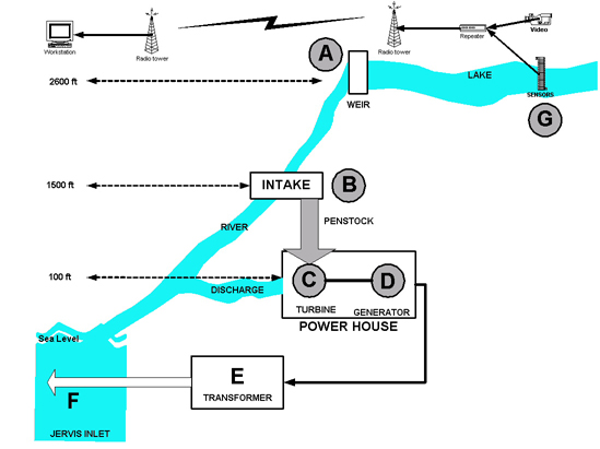
Diagram by Hitzcomm showing the main components of the system. Additional RTU's can be added as necessary.
The power cable runs under Jervis Inlet to Malibu. |
Requirements:In order to correctly operate a complex system such as Malibu Hydro, the following topics must be addressed.
McCannel Lake is the reservoir which stores the water required by the turbine. This lake is filled by rain and snow melt, so the level varies throughout the year. In cold winters, and in dry summers, the level will drop as consumption exceeds infilling. The small weir at the end of the lake was built to store additional water for such times. A large valve in this weir is adjusted to permit sufficient flow from the lake to run the hydro system and maintain a level of water in the creek downstream from the intake dam. The lake RTU permits Malibu to monitor the lake reserves and make decision based on the water level. Water level behind the weir is measured, as well as the overflow over the weir. In addition, we monitor air and water temperature, solar battery charger voltage, and can control a remote camera. At the intake, the second RTU monitors the actual level of water in the intake dam and penstock manifold. It is vital that this level is maintained at or above the dams spill way. If the level falls below the spill way, it means the demand is exceeding the supply and the camp load must be reduced. Failure to do so will permit air to enter the system which on a high head hydro site is extremely bad for the turbine as it can cause cavitation and destruction of the turbine blades. As at the lake, temperatures and voltages are also measured. Remote Control It may become necessary to remotely control the gate valve which drains McCannel Lake. At present, reaching the lake is a lengthy hike in summer and virtually impossible in winter. With some minor upgrades to the power supply at the lake RTU, motorized control of this large valve will be possible. It will work like this: The operator clicks on the "Open Valve" button on the computer screen. A command is sent up to the RTU which activated the motor in a forward direction for ... say 30 seconds, which opens the valve one inch. The motor then shuts down until a second command is issued. This is a proven method of controlling a valve, and reduces the possibility of the valve being fully opened or closed. A similar control system was installed on a plant in Alaska, and has worked well. As the intake dam is 1200 vertical feet below the lake, it would take some time for the increase to be observed. A calibrated table would relate valve settings to river flow, indicating how much to open the valve. A camera aimed at the valve would also provide visual feedback. A similar system could be implemented at the intake dam if needed. At present, power for the Dam RTU is provided by a small 12 volt DC hydro generator. This generator charges a large battery and so sufficient energy is available for a number of loads. At present this consists of the Intake RTU and camera. A second camera looking down on the dam is planned, and perhaps a spot light for night viewing. One thought was to provide heating to the valves, but this is impractical due to their thermal mass. Monitor the generating equipment The main power house PLC takes care of most of this so we did not add additional sensors at this time. These would have been:
Manage Loads The hydro system will produce at most, 580 kilowatts of electrical energy. This is a considerable increase over the diesel gen set which would produce 125 kw at maximum output. However, diesel engines produce a great deal of heat, and in addition to the 125 kw of electrical energy, there was on the order of 90 kw of heat produced which was used to heat the camps domestic water. With the hydro plant online, all electrical and heating needs must now be met by water power. As camp expands with new buildings, cabin space heaters, in floor heating, hot water tanks and other smaller loads, the 580 kw maximum could soon be reached. Another potential problem could be insufficient water to produce the 580 kW. This scenario was considered in the design stage, and the lake dam was built to store additional water to carry through dry times. At full output, there should be sufficient water to operate for approximately 80 days. This figure was calculated based on stored water and daily demand, but has yet to be calibrated against actual operation. Enter load management. Load management is a computer based method of automatically controlling loads, and hence water consumption, based on measurements of available water and present load. Without management, black outs are likely in times of high demand unless an operator was constantly monitoring the water levels, peak loads, and making adjustments as necessary. Load management was installed on the diesel generators as early as 1987, and was upgraded in 2003. This simple solution controlled 25 kW of electric water heater load and was instrumental in preventing brown outs. It sensed total current produced, and shed the electric heater load as the total current reached programmed maximums. Brown outs are more dangerous than black outs as loads continue to run but often at very high currents and lower voltages and lower frequencies which can quickly burn out motors and transformers, depending on the voltage / current relationship. With the hydro system, the large hot water tanks will be controlled in stages of no more that 25 kw per stage. This will minimize surges on the electrical system, and permit the turbine governor to keep up with load changes. |
 |
 |
|
 |
AlternativesWithout a radio based SCADA system, the only way to know what is going on at the lake would be to take a boat across Jervis Inlet, and hike up to the lake and take measurements. As the lake a minimum 2 hour hike in good conditions, and almost impossible to reach in winter, this is impractical.The lower intake dam is accessible via the two mile long access road, with an elevation gain of 1,400 feet. At present there is a truck available which is a huge help, but as the access road deteriorates, this may not be possible. This is what happened on the Helena creek road. The power house is fully automatic, incorporating a built in computer (PLC) to control all the various functions and monitor alarms. No link to Malibu was included in the contract, so for the most part, Malibu was blind. Only a system shutdown would promt Malibu of a problem. Should an emergency arise in which the system must be shut down immediately, it presently requires a trip across the inlet, taking a minimum 20 minutes to reach the power house. A shutdown or emergency on a dark and stormy night can be a dangerous and unpleasant undertaking. Since the SCADA system costs were not included in the overall budget, development proceeded slowly to test the design and to demonstrate the worth of such a system. Once the hydro project was a certainty, the rest of the RTU's and equipment was purchased knowing that such a system was going to be an essential component. The first year consisted of a basic lake level monitor and a text readout at Malibu. The RTU was battery powered and was designed to run for one year. This test was successful, and verified the radio circuit would be reliable in all types of weather. |
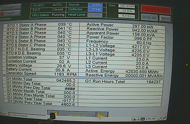
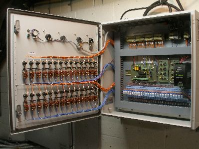
Human Machine Interface - HMIThe data collected from the RTU's is displayed on a computer at Malibu running a visual basic program created by Chaz Hitz, of Sitka2 Publishing fame. This HMI (human machine interface) program displays all sensor readings, accepts user inputs to control various remote devices, logs all the data to a file, and conditions all data for subsequent uploading to this web site.The interface program will run on any windows PC. The 'System Data' section of this web site fetches the data from the server, and using a data manipulation language called PHP, places the data into the correct location in the system data tables presented. Time and date stamping is done by means of some script routines and is fully automatic. Here is what the Malibu HMI looks like. |
|
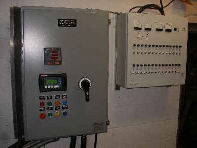
ComponentsThe following are the main components:
|
|
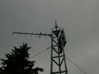
Lake RTU
McCannel Lake fills a large cirq, or bowl, at the 2400 foot elevation cut into the mountain from past glacial activity. A dam was constructed at the mouth of the lake to hold the water at the normal high water mark following periods of rain. The dam, or weir, regulates the flow from the lake in such a way that the lake does not drain out as quickly as it did previously. The RTU was installed to measure the water level, weir overflow, water and air temperature, battery voltage, and internal clock. With this data, we can plot the rate of change in lake level and make decisions on when and if we need to regulate the flow from the lake. The RTU consists of the computer controller mounted five feet up a steel tower totaling 20 feet in height. Toward the top of the tower, the solar panel is aimed south out over the lake, and the radio antenna is pointed to Malibu. The tower is guyed with steel cables to brace it against high wind and snow drift. Sufficient sunlight reaches the site to permit the use of solar panels to produce the electricity required by the RTU. The solar panel produces 1.2 Amps in full sun, and the charge is regulated by a shunt type solar regulator. A 7 amp hour battery stores sufficient charge to power the RTU through the winter months with minimal charging. It is designed to operate for 20 days with no charge at all. |
|
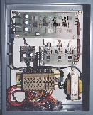
Intake Dam RTU
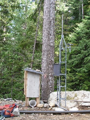 Dam RTU |
The intake dam is the point where the pressure pipeline picks up the water for the turbine.
Here we need to measure the water level in the dam, the water level in the air breather stack just below the dam and the level overflowing the dam spillway.
Also measured are air and water temperature, battery voltage and camera status. Other inputs and outputs are available as needed. The RTU is powered by a small micro hydro generator with water provided by a 3 inch diameter line operating under a drop or head of 60 feet. This generator produces about 60 watts of power. |
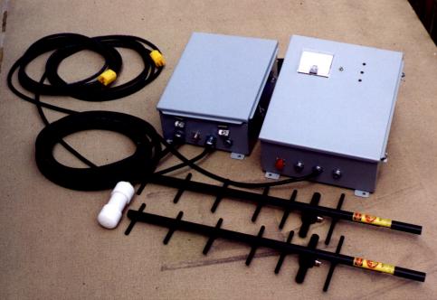 Long range wireless head level control system for Alaska Hydro project. |
|